Modern televisions depend on thin LED strips for brightness, uniformity, and stable picture performance. TrendForce estimated nearly 201 million global TV shipments in 2024, showing how many displays now rely on LED backlighting. When a screen turns dark but still produces faint images, the backlight circuit deserves careful testing.
This guide explains how to test tv led backlight strip with multimeter using practical, low-cost checks. You will learn how to inspect connectors, measure diode behavior, compare strip sections, and recognize misleading readings. A working technician’s habit matters here: disconnect power, discharge capacitors, and photograph every connector before touching the panel. Small mistakes can damage fragile diffuser sheets or create a false diagnosis.
As repair educator Ben Heck has often emphasized in electronics work, “Measure twice before replacing the part.” That principle fits LED-backlight troubleshooting, even when the exact fault seems obvious. A multimeter can reveal an open LED, an unexpected short, or a broken connection. It cannot explain every symptom alone. That is where this guide needs honesty: resistance mode may show inconsistent values, and some strips require a dedicated LED tester for reliable confirmation. Even experienced technicians can misread a bright flash as a healthy strip. Treat each measurement as evidence, not proof. Safety comes first, especially around the television’s power-supply section, where dangerous voltage may remain after unplugging.
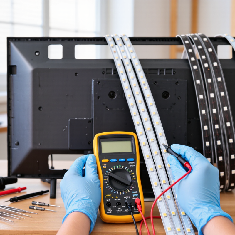
Identify LED Strip Topology: 3 V LEDs and 60–200 V String Ranges
5 Tips: How to Test TV LED Backlights With a Multimeter
Identify LED Strip Topology: 3 V LEDs and 60–200 V String Ranges
Tip 1: Understand the circuit before testing. Many TV backlights use LEDs rated near 3 V each, connected in series. A complete strip can require 60–200 V from its LED driver. My earlier mistake was expecting a continuity beep across the entire strip. A standard multimeter often cannot supply enough voltage to illuminate a long series chain. A silent meter does not always mean a failed strip.
Tip 2: Disconnect power and allow the television to discharge. Remove the rear cover carefully, because the panel and diffuser layers are easily damaged. Set the meter to diode mode, then touch the probes across one LED or an accessible test point. A healthy individual LED may show a forward-voltage reading or faint glow. Reverse the probes if necessary. Do not test the driver output casually; its voltage can be hazardous.
Tip 3: Check polarity, connectors, and section resistance. An open reading may indicate a broken LED, cracked solder joint, or loose connector. A short reading can suggest a bypassed or damaged LED, but resistance mode is not conclusive. I have trusted that reading before, and it led me toward the wrong repair. Compare matching strips and inspect darkened lenses or brown spots. For full-string testing, use a suitable backlight tester with controlled voltage and current.
5 Tips How to Test TV LED Backlights With a Multimeter? - Identify LED Strip Topology: 3 V LEDs and 60–200 V String Ranges
| Tip |
Test Area |
Recommended Multimeter Mode |
Typical Reading or Range |
What the Result Indicates |
Practical Action |
| 1 |
Identify the LED strip topology |
Diode-test mode with the TV unplugged |
One white LED: approximately 2.5–3.6 V forward voltage |
A single LED or a short parallel section may light faintly if the meter provides enough test current. |
Record the number of LEDs connected in series. Do not assume that every strip uses the same series/parallel arrangement. |
| 2 |
Estimate the voltage of a series string |
Use the diode-test function only for individual sections; use a suitable DC-voltage range for powered-driver measurements. |
Common TV string outputs: approximately 60–200 V DC, depending on the number of series LEDs |
A long series string can require far more voltage than a standard multimeter diode test can supply. |
Never conclude that a strip is open solely because the diode-test display shows “OL.” The meter may not have sufficient compliance voltage. |
| 3 |
Check for an open LED or open strip |
Diode mode across each accessible LED or strip section, with power disconnected |
A healthy individual LED generally shows a forward-voltage value; “OL” in both probe directions suggests an open circuit. |
An open LED, cracked solder joint, or broken copper track can interrupt the entire series string. |
Compare readings between similar sections. Inspect solder joints and connector contacts before replacing the strip. |
| 4 |
Check for a shorted LED |
Diode mode and resistance mode, with power disconnected |
A shorted LED may show a very low voltage drop or unusually low resistance in both directions. |
The backlight may still operate, but the affected area can be darker, and the driver may regulate abnormally. |
Test the LED in circuit and, where necessary, confirm the result after isolating one side of the component. |
| 5 |
Measure the LED-driver output carefully |
DC-voltage mode, only when the TV is energized and the meter is rated for the expected voltage |
Approximately 60–200 V DC may be present across a long LED string; voltage can change when the load is connected or disconnected. |
High output with no illumination may indicate an open string. Very low or pulsing output may indicate driver protection, a short, or a control fault. |
Measure across the correct LED-output terminals, keep probe tips steady, and compare the reading with the string configuration and service documentation. |
Safety note: TV LED-backlight circuits can contain hazardous DC voltages, especially when the LED string is open. Disconnect AC power before resistance or diode testing, discharge capacitors appropriately, use insulated probes, select a properly rated meter, and avoid touching the circuit while powered. A diode-test reading is a diagnostic indication, not a substitute for the LED driver's specified output.
Prepare Safely: Unplug the TV and Follow IEC 61010-1 CAT II Practices
5 Tips: How to Test TV LED Backlights With a Multimeter?
Prepare Safely: Unplug the TV and Follow IEC 61010-1 CAT II Practices
Unplug the television before removing its rear cover. Disconnect the power cord, press the power button, and wait several minutes. Capacitors may still hold energy. IEC 61010-1:2010+A1:2016 defines CAT II equipment for measurements on appliance circuits connected to low-voltage installations. CAT II does not make a charged circuit harmless. I learned this the cautious way.
Inspect the multimeter, probes, and insulation before testing. Use intact leads with suitable voltage and CAT II ratings. Confirm the meter works on a known source, then disconnect it again. Select resistance or diode mode only after checking for zero voltage. Never measure resistance on an energized board. Never short capacitor terminals with a screwdriver. A controlled discharge method is safer. The U.S. National Fire Protection Association’s NFPA 70E, 2024 edition, stresses approach boundaries and proper verification before electrical work.
Find the LED connector and photograph its position before removal. Test each strip section gently, using the lowest practical range. Some LED strings will not illuminate with a standard diode setting. That result is not proof of failure. Use a dedicated LED tester when the circuit requires higher forward voltage. Keep one hand away from the chassis. Work on a dry, nonconductive bench. The International Labour Organization reported nearly three million work-related deaths annually in its 2023 safety estimates. Home repairs are smaller tasks, but careless habits scale quickly.
Set Diode Mode: Expect About 2.8–3.4 V Forward Voltage per LED
5 Tips How to Test TV LED Backlights With a Multimeter
Disconnect the television from mains power before opening the rear panel.
Allow the capacitors time to discharge. A multimeter cannot make an unsafe circuit safe.
Tip one:
set the meter to diode mode, not resistance mode. Most white backlight LEDs show about 2.8–3.4 V forward voltage each. This range is a guide, not an absolute rule. Temperature, LED design, and meter accuracy can change the reading.
Tip two:
identify the positive and negative test points carefully. Touch the red probe to the anode and the black probe to the cathode. A healthy LED may glow faintly. Keep probes steady. If the display shows open circuit, reverse the probes once. If both directions remain open, the LED or its connection may be damaged.
Tip three:
test each accessible LED separately when possible. A complete strip can contain many LEDs in series, exceeding the meter’s output voltage.
Tip four:
compare readings between several LEDs. One noticeably different value deserves closer inspection. A shorted LED may show an unusually low reading, but the surrounding circuit can affect measurements.
Tip five:
avoid pressing hard against delicate contacts. I have seen small test pads lift from the strip during rushed checks. That mistake is easy to make.
Record each reading, inspect dark spots, and remember that a normal diode result does not prove the entire backlight system works. Loose connectors, driver faults, and intermittent solder joints can still cause a dark screen.
Test Strip Continuity: Compare Forward Readings Across Parallel LED Branches
5 Tips How to Test TV LED Backlights With a Multimeter?
Unplug the television and allow the power board to discharge before opening the panel.
Remove the rear cover carefully, then disconnect the LED backlight connector. Never test a powered circuit in continuity mode. Set the multimeter to diode mode, and touch the probes to one LED branch at a time. Keep the probe polarity consistent. A healthy branch may show a forward-voltage reading, while an open branch often displays “OL.” Some branches will not light because the meter cannot provide enough voltage for several series LEDs.
Test strip continuity by comparing forward readings across parallel LED branches. Record each result instead of trusting one measurement. Similar readings suggest the branches share a comparable electrical path. A noticeably higher reading, unstable number, or “OL” result may indicate an open LED, cracked solder joint, or damaged connector.
Reverse the probes briefly. The reading should usually change or remain blocked. It should not be treated as a perfect diagnosis.
I once blamed a faulty LED after seeing no light in diode mode. The meter voltage was simply too low. That mistake matters. Continuity mode can also beep through other circuit paths, creating false confidence. Inspect dark spots, loose contacts, and burned lenses after electrical testing. If one branch differs greatly, compare it again with the connector isolated. Do not use resistance readings alone. Replace or repair parts only after confirming the result safely.
Interpret Results: Open LEDs, Shorts, and Balanced Current-Draw Patterns
Testing TV LED backlights with a multimeter requires patience and controlled measurements. Unplug the television, allow the power board to discharge, and remove the backlight connector before testing. Use diode mode across each LED or strip section. A healthy LED may show a forward-voltage reading and faintly glow, depending on the meter. Some meters cannot provide enough voltage, so a blank display does not always prove failure.
An open LED usually shows “OL” or no stable reading in both probe directions. This often creates a dark section, while other LEDs remain illuminated. A shorted LED may show extremely low resistance or conduct in both directions. It can also cause repeated shutdowns because the driver detects an abnormal load. Do not confuse a short with a normal forward reading. Probe contact matters.
Current patterns reveal more than one isolated reading. With a current-limited supply and the correct test voltage, healthy strips should draw similar current. Balanced readings suggest even LED loading and consistent brightness. One strip drawing sharply less current may contain an open circuit. A higher reading can indicate leakage or a shorted section. I once blamed the LEDs when a loose connector caused unstable values. That mistake still matters. Repeat each test, reverse the probes, and compare identical strips under the same conditions. Avoid powering an unprotected strip directly from a high-voltage source.
Conclusion
Learning how to test tv led backlight strip with multimeter begins with understanding the strip’s design. Individual LEDs commonly operate at about 3 V, while a complete series string may require roughly 60–200 V. Before testing, unplug the television, allow time for stored charge to dissipate, and follow suitable IEC 61010-1 CAT II safety practices. Remove or access the backlight assembly carefully, avoiding pressure on the screen.
Set the multimeter to diode-test mode and check each LED or accessible branch. A healthy LED will typically show a forward-voltage reading of approximately 2.8–3.4 V, although the exact value can vary. Compare readings across parallel branches and look for consistent results. An open LED or strip may produce no reading, while a shorted LED may show an unusually low value. Balanced readings and similar current-draw patterns generally indicate normal operation, whereas significant differences can help identify a failed section. Always interpret measurements with the strip’s topology in mind.
 Junhengtai Electronic
